


Serviços Personalizados
Artigo
 pdf em Inglês
 Artigo em XML
 Referências do artigo
 Enviar este artigo por email
Links relacionados
Compartilhar

 Permalink
Stomatos
versão impressa ISSN 1519-4442
Stomatos vol.18 no.34 Canoas Jan./Jun. 2012
SCIENTIFIC ARTICLE
Stress to the Bone around Orthodontic Implants in the Mandibular Molar Region: A Finite Element Evaluation
Estresse ao Osso em Torno de Implantes Ortodônticos na Região de Molares Inferiores: uma Avaliação por Elementos Finitos
Rogério Coelho de Aguiar1; Leandro Luis Corso2; Naiara Leites Larentis1; Rogério José Marczak2; Vania Fontanella1
1Graduate Program in Dentistry, Universidade Luterana do Brasil, Canoas, Brazil.
2Mechanical Engineering Department, Universidade Federal do Rio Grande do Sul, Porto Alegre, Brazil.
ABSTRACT
Mini-screw implants have been commonly used for orthodontic anchorage. However, the behavior of implants may vary according to their location, inclination, loading position and loading direction. The objective of this study was to apply finite element to analyze stress distribution around mini-implants inserted into the buccal cortical bone, in the inferior molar region, when a force of 3 N was applied, varying implant inclination and loading direction, also simulating immediate loading and osseointegration conditions. We carried out a threedimensional analysis of a human cadaveric mandible and of a 9 mm length, 1.5 mm diameter titanium implant. The implant model was introduced into the buccal cortical bone, between the first and second mandibular molars. Finite-element analysis of the implant-bone structure was carried out applying a constant force of 3 N at varying angles (15, 30, 45, 60, 75, and 90 degrees), and in five different positions along the bone surface axis (perpendicularly, vertically at ± 10 degrees, and horizontally at ± 20 degrees). Out of all combinations tested, stress affected only the cortical bone, not being intense enough to cause cortical bone resorption. Stress distribution varied slightly (8.55 to 38.74 Mpa) due to implant inclination and loading direction. Immediate loading generated greater tensions (12.70 to 38.74 Mpa) when compared to osseointegration (8.55 to 21.44 Mpa). A force of 3 N did not result in a tension that could cause cortical bone resorption. Immediate loading resulted in greater tensions to the bone, regardless of implant inclination and loading direction.
Keywords: dental implants, finite element analysis, Orthodontics.
RESUMO
Mini-implantes têm sido utilizados para ancoragem ortodôntica e seu comportamento pode variar de acordo com a sua localização e inclinação, com a posição e a direção da carga aplicada. Este estudo analisou a distribuição de tensões ao osso em torno de mini-implantes inseridos no osso cortical na região de molares inferiores, quando uma carga de 3 N é aplicada, variando a inclinação do implante e a direção da força,assim como situações de carga imediata e osseointegração. Uma mandíbula humana e um implante de titânio com 9 mm de comprimento e 1,5mm de diâmetro foram modelados, com o implante introduzido na face vestibular entre o primeiro e o segundo molares. Este modelo foi analisado pelo método de elementos finitos aplicando força constante de 3N com angulagens de 15, 30, 45, 60 e 75 graus, com o implante perpendicular ao osso e com inclinação vertical de 10 graus e horizontal de 20 graus. Em todas as combinações testadas a tensão afetou apenas o osso cortical, porém não apresentou intensidade suficiente para resultar em reabsorção óssea. Sua distribuição variou (8,55 a 38,74 Mpa) em função da inclinação do implante e da direção da carga. A situação de carga imediata gerou maiores tensões (12,70 a 38.74 Mpa) quando comparada à osseointegração (8,55 a 21,44 Mpa). Conclui-se que uma força de 3N não resulta em tensão que possa causar reabsorção da cortical óssea e que a carga imediata produz maior tensão ao osso, independentemente da inclinação do implante e da direção da força.
Palavras-chave: implantes dentários, análise por elementos finitos, Ortodontia.
INTRODUCTION
The use of dental implants is an excellent alternative to conventional orthodontic anchorage methods, especially in cases of a small amount or poor quality of dental elements, in the impossibility of using extraoral anchorage, or in the case of uncooperative patients1-3. In the past few years, the design of orthodontic implants has improved; consequently, they have become smaller and easier to use. The advantages of mini-screw implants are their low cost, uncomplicated insertion and removal, and great versatility. Mini-screw implants allow for insertion at several sites, which is an advantage in terms of orthodontic planning4,5. The criteria for assessment of successful implantation of mini-screws are no signs of infl ammation, absence of clinical mobility, and ability to support anchorage during orthodontic treatment6,7.
Mini-screw implants have been used as anchorage in several orthodontic movements, such as intrusion, extrusion, rotation, mesial and distal bodily movements, and uprighting movement. In most studies, the force applied is between 0.3 and 2.5 N, similar to the force applied normally in orthodontics when such movements are performed1. A small force (0.1 to 0.2 N per tooth) is recommended for intrusion of anterior teeth, but a greater force (1.5 to 2 N per tooth) is necessary for intrusion of posterior teeth5.
Finite element analysis (FEA) is a numerical analysis method employed in mechanical engineering, in which the structure being investigated is determined by a give number of elements. The mechanical behavior of each element is described by different equations, which are, in their turn, solved by computational software. FEA can be used to evaluate implant design, without the risks and costs associated with clinical assays8. Moreover, experimental studies have confirmed that despite the simplifications of linear analysis with FEA, the method is reliable and efficient, and can be applied in investigations in implantodontics9-12. FEA also allows collecting data on the distribution of measured tensions, which, in its turn, allows for identifying critical points. This numerical analysis, combined with clinical evaluation, can bring significant advancements in the understanding of different conditions that affect the oral cavity13.
However, little has been done in the sense of employing mechanical analyses to qualify and quantify the tension status of implants. Therefore, there is a vast field of scientific investigation, which may yield a more robust knowledge base on tensions and orthodontic implants. The aim of this study was to apply FEA to analyze stress distribution around mini-implants inserted into the buccal cortical bone, in the inferior molar region, when a force of 3 N was applied, varying implant inclination and loading direction.
METHODOLOGY
Modeling
This study was approved by the institutional Research Ethics Committee. An edentulous human dry mandible was digitized through a tridimensional scanner (Atos Standard, Gom mbH, Braunschweig, Germany) and its surface was solidified (SolidWorks 2005, SolidWorks Co., Concord, MA, EUA). The distribution between the cortical and medullary bones of different regions was established using dimensions obtained from computed tomography scan data of adult individuals. The mesh generated for the initial global model had 37,356 threads and 20,338 elements. This analysis employed three types of elements: 10-Node Quadratic Tetrahedron, Quadratic Triangular Contact and Quadratic Triangular Target.
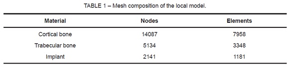
According to Roychowdhury et al14, the modeling of the whole mandible does not affect results, since significant stress effects occur only near the site of loading. Our pilot study, a global assessment of the computational model, corroborated this finding. As a result, the model was split into a local model so as to refine the mesh into 21,362 threads and 12,487 elements, distributed according to Table 1.
The implant had 9 mm in length, and 1.5 mm in diameter (Conexão, São Paulo, Brazil). It was made of pure titanium, with no surface treatment. The implant model was inserted into the buccal cortical bone between the first and second mandibular molars on the left side. The implant simulated traction and/or intrusion of a molar tooth on that same side. The model had 1.7 mm of cortical bone, and 9.7 mm of trabecular bone. Thus, the implant was inserted 1.7 mm into the cortical bone and 4 mm into the trabecular bone; it did not reach the lingual cortical bone. The difference in length (3.3 mm) corresponds to the implant pillar located externally in relation to the bone.
Materials Properties
The mechanical characteristics of the human mandible were obtained from different authors12-15, according to Table 2. Due to a lack of more accurate models, the cortical bone, the trabecular bone, and titanium were considered to have an isotropic, homogeneous, and linearly elastic behavior. Although different bone qualities result in different biomechanical behaviors16, we adopted a standard bone structure with two types of bone (cortical and medullary)17,18.

Finite Element Analysis
A finite element analysis of the implant-bone structure was carried out using Ansys 9.0 system (Ansys Inc., Houston, PA, USA), by the Group of Applied Mechanics, Universidade Federal do Rio Grande do Sul, Brazil. The analysis determined the areas of stress on the bone tissue around the implant. Von Mises equivalent stress values were used to assess critical areas of the implant-bone structure, and to allow for comparison with other studies.
Load
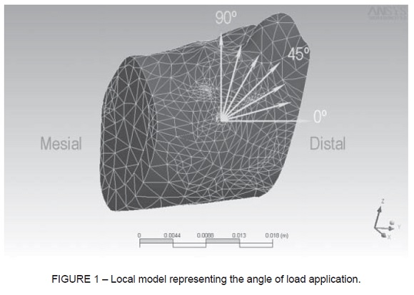
Figure 1 shows a three-dimensional illustration of the bone structure and inserted implant. The bone deformation was evaluated after application of different loading directions (15, 30, 45, 60, 75, and 90 degrees), and a constant load of 3 N (300 g). The load was applied according to five positions of the implant axis, in relation to the bone surface: perpendicular to the axis; at 10 degrees from the vertical axis, either cervical or apical inclination; and at 20 degrees from the horizontal axis, either mesial or distal inclination.
Two situations of implant-bone contact were simulated. In total osseointegration, or late loading, there is direct and continuous contact at the implant-bone interface (no relative mobility between the surfaces of the material)12,15. In immediate loading, mobility at the implant-bone interface may occur11,19,20.
RESULTS
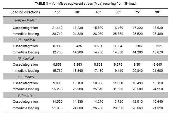
Table 3 shows the Von Mises equivalent stress values that resulted from the application of 3N load on all combinations analyzed in this study. The distribution of stress on the bone was seen on buccal surface, axial and bucco-lingual cross-sections. The variation in the area under stress was minimal, both in relation to the implant inclination and loading direction. The greater equivalent stress was confined to the cortical bone and, in the present study, was not intense enough to cause cortical bone resorption (103.37± 20.9 Mpa)21.
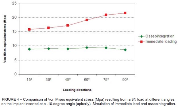
The comparison of equivalent stress as a function of loading direction is represented in Figure 2 to Figure 6, according to the implant position (perpendicular or inclined). The simulation of immediate loading resulted constantly in higher tension values than the simulation of osseointegration. The greater tensions (>30 MPa) were observed when an implant inserted perpendicularly to the buccal surface of the mandible is submitted to a load at a 15 degree angle (Figure 2), and when an implant inserted at 20 degrees from the vertical axis (mesially) is submitted to a load at a 60 degree angle (Figure 5). Both cases simulate immediate loading.
Smaller equivalent stress is observed when the implant is inserted with apical, cervical, or mesial inclination in osseointegration. In situations of immediate loading, the more favorable results were observed in implants with cervical or apical inclination.


DISCUSSION
Orthodontic implants with reduced length and diameter, as those applied in the present study, withstand orthodontic stress provided that an appropriate design and implant-bone interface exist. The tensions must be distributed onto the adjacent bone tissue physiologically, so as to avoid surgical trauma or iatrogenic resorption1. Implant size must also be compatible with the amount of bone tissue available at the implant site.
Considering that the implant analyzed is used only as orthodontic anchorage, and given the several clinical situations that could have been simulated, we chose to insert the implant at the site corresponding to the buccal cortical bone between the first and second mandibular molars. The orthodontic movements to be analyzed were mesial shift of the third mandibular molars, and intrusion of the first and second mandibular molars.
Umemori et al22 also chose the region between the first and second mandibular molars to introduce a skeletal anchorage system of mini-plates on the buccal cortical bone, for open-bite correction, and obtained satisfactory results. For this site, the use of small implants is recommended, in view of the uncomplicated insertion and removal of mini-implants, in addition to their great versatility and of the site being in close proximity to the inferior alveolar nerve and to the roots of adjacent teeth.
The possibility of intrusion of posterior teeth in orthodontic practice offers great treatment benefits. According to Park et al5 mini-implants may provide anchorage for intruding mandibular molars approximately 0.5 to 1 mm per month, without damaging the dental pulp or inducing root resorption. As a result, mini-implants can avoid the need for crown reduction, endodontic treatment, or even the extraction of an extruded opposing tooth.
Cheng et al6 analyzed 140 mini-implants in terms of orthodontic anchorage, and did not find statistically significant differences between the lengths of implants (5 to 15 mm). According to the authors, extrusive forces on mini-implants should be avoided since they may induce mobility and, consequently, implant failure. In this study, we did not carry out a separate analysis of extrusive forces. However, it is possible that these forces occur when the implant is inclined in the same direction as the applied load.
The different inclinations of the mini-implant in relation to bone surface determine a small variation in the area under stress, according to Gedrange et al8. Horizontal loading shifted the deformation from the trabecular to the cortical bone. Considering that excessive load is generated around inclined implants, resulting in microfractures in the bone, which, in turn, result in mobility and eventual implant failure. Watanabe et al23 observed more pronounced implant tension at a 45 degree angle. The maximum horizontal angle for the model analyzed was 20 degrees, due to anatomical limitations caused by the mandibular surface and contact with the implant.
All loading direction simulations in this study showed greater tension on the cortical bone adjacent to the neck of the orthodontic implant. This finding is corroborated by other studies that used radiographic examinations, experimental clinical investigations, and numerical analysis of different conventional implant designs11,15. The concentration of tension on the crest of the implant may induce pathological bone resorption, and it is influenced by the thickness of the cortical bone24. This may lead to failure of osseointegration, being comparable to clinical bone resorption observed around implants25.
CONCLUSION
The application of a load of 3N did not generate enough tension to cause cortical bone resorption. Moreover, immediate load generated greater tensions, regardless of implant inclination and of loading direction.
REFERENCES
1. Favero L, Brollo P, Bressan E. Orthodontic anchorage with specific fixtures: related study analysis. Am J Orthod Dentofac Orthop. 2002;122(1):84-94. [ Links ]
2. Sarmah A, Mathur AK, Gupta V, Pai VS, Nandini S. Finite element analysis of dental implant as orthodontic anchorage. J Contemp Dent Pract. 2011;12(4):259-64. [ Links ]
3. Jasmine MI, Yezdani AA, Tajir F, Venu RM. Analysis of stress in bone and microimplants during en-masse retraction of maxillary and mandibular anterior teeth with different insertion angulations: a 3-dimensional finite element analysis study. Am J Orthod Dentofacial Orthop. 2012;141(1):71-80. [ Links ]
4. Deguchi T, Takano-Yamamoto T, Kanomi R, Hartsfield JK Jr, Roberts VE, Garetto LP. The use of small titanium screws for orthodontic anchorage. J Dent Res 2003;82(5):377-81. [ Links ]
5. Park YC, Lee SY, Kim DH, Jee SH. Intrusion of posterior teeth using mini-screw implants. Am J Orthod Dentofac Orthop. 2003;123(6):690-4. [ Links ]
6. Cheng S, Tseng I, Lee J, Kok S. A prospective study of the risk factors associated with failure of mini-implants used for orthodontic anchorage. Int J Oral Maxillofac Implants. 2004;19(1):100-6. [ Links ]
7.Chatzigianni A, Keilig L, Duschner H, Götz H, Eliades T, Bourauel C. Comparative analysis of numerical and experimental data of orthodontic mini-implants. Eur J Orthod. 2011;33(5):468-75. [ Links ]
8. Gedrange T, Bourauel C, Köbel C, Harzer W. Three-dimensional analysis of endosseous palatal implants and bones after vertical, horizontal, and diagonal force application. Eur J Orthod. 2003;25(2):109-15. [ Links ]
9. Keyak JH, Fourkas MG, Meagher JM, Skinner HB. Validation of the automated method of three-dimensional finite element modelling of bone. J Biomed Eng. 1993;15(6):505-9. [ Links ]
10. Benzing UR, Gall H, Weber H. Biomechanical aspects of two different implantprosthetic concepts for edentulous maxillae. Int J Oral Maxillofac Implants. 1995;10(2):188-98. [ Links ]
11. Murphy WM, Williams KR, Gregory MC. Stress in bone adjacent to dental implants. J Oral Rehabil. 1995;22(12):897-903. [ Links ]
12. Baiamonte T, Abbate MF, Pizzarello F, Lozada J, James R. The experimental verification of the efficacy of finite element modeling to dental implant systems. J Oral Implantol. 1996;22(2):104-10. [ Links ]
13. Cruz M, Wassal T, Toledo EM, Barra LP, Lemonge AC. Three-dimensional finite element analysis of a cuneiform-geometry implant. Int J Oral Maxillofac Implants. 2003;18(5):675-84. [ Links ]
14. Roychowdhury A, Pal S, Saha S. Stress analysis of an artificial temporal mandibular joint. Crit Rev Biomed Eng. 2000;28(3-4):411-20. [ Links ]
15. Akpinar I, Demirel F, Parnas L, Sahin S. A comparison of stress and strain distribution characteristics of two different rigid implant designs for distal-extension fixed prostheses. Quintessence Int. 1996;27(1):11-7. [ Links ]
16. Lekholm U, Zarb GA. Patient selection and preparation. In: Branemark P I, Zarb GA, Albrektsson T. Tissue integrated prostheses, osseointegration in clinical dentistry. Chicago: Quintessence; 1985. p. 199-209. [ Links ]
17. Meijer GJ, Starmans FJ, de Putter C, van Blitterswijk CA. The influence of a flexible coating on the bone stress around dental implants. J Oral Rehabil. 1995;22(2):105-1. [ Links ]
18. Gallas MM, Abeleira MT, Fernández JR, Burguera M. Three-dimensional numerical simulation of dental implants as orthodontic anchorage. Eur J Orthod. 2005;27(1):12-6. [ Links ]
19. Weinstein AM, Klawitter JJ, Anand SC, Schuessler R. Stress analysis of porous rooted dental implants. J Dent Res. 1976;55(5):772-7. [ Links ]
20. Wadamoto M, Akagawa Y, Sato Y, Kubo T. The three-dimensional bone interface of an osseointegrated implant. I: A morphometric evaluation in initial healing. J Prosthet Dent. 1996;76(2):170-5. [ Links ]
21. Kotha SP, Guzelsu N. Tensile damage and its effects on cortical bone. J Biomech. 2003;36(11):1683-89. [ Links ]
22. Umemori M, Sugawara J, Mitani H, Nagasaka H, Kawamura H. Skeletal anchorage system for open-bite correction. Am J Orthod Dentofac Orthop. 1999;115(2):166-74. [ Links ]
23. Watanabe F, Hata Y, Komatsu S, Ramos TC, Fukuda H. Finite element analysis of the influence of implant inclination, loading position, and loading direction on stress distribution. Odontology. 2003;91(1):31-6. [ Links ]
24. Kitagawa T, Tanimoto Y, Nemoto K, Aida M. Influence of cortical bone quality on stress distribution in bone around dental implant. Dent Mater J. 2005;24(2):219-24. [ Links ]
25. Greco, GD, Jansen WC, Landre Junior J, Seraidariand PI. Stress analysis on the free-end distal extension of an implant-supported mandibular complete denture. Braz Oral Res. 2009; 23(2):182-9. [ Links ]
 Corresponding Author:
Vania Regina Camargo Fontanella
Programa de Pós Graduação em Odontologia
Universidade Luterana do Brasil
Av. Farroupilha, 8001
CEP 92425–900 – Canoas, RS, Brazil
Phone: +55-51–34629512 / +55-51–34629510
E-mail:vaniafontanella@terra.com.br
