


Serviços Personalizados
Artigo
 pdf em Inglês
 Artigo em XML
 Referências do artigo
 Enviar este artigo por email
Links relacionados
Compartilhar

 Permalink
Brazilian Journal of Oral Sciences
versão On-line ISSN 1677-3225
Braz. J. Oral Sci. vol.14 no.2 Piracicaba Abr./Jun. 2015
ORIGINAL ARTICLE
Rotation axis of the maxillary molar and maximum tooth movement according to force direction
Carla Scanavini CrocI; Paulo Henrique Ferreira CariaI
I Universidade Estadual de Campinas - UNICAMP, Piracicaba Dental School, Department of Morphology, Piracicaba, SP, Brazil
Abstract
Aim: To evaluate the correlation between the maxillary molar rotation center and the direction of the maximum tooth movement according to the force direction using three-dimensional finite element analysis (3D-FEA). Methods: Computed tomography of a human tooth was used to build a finite element model, which comprised the cancellous and cortical bones, the periodontal ligament and the tooth. After applying lateral and posterior boundary conditions, a 1 N force was applied to the mesial and lingual faces of the maxillary molar to simulate buccal and distal tipping forces on the tooth. Results: The initial displacement of the maxillary first molar was greater for distal tipping than for buccal tipping. The rotation axis for distal tipping in this simulation was located on the furcation of the first molar. For buccal tipping this axis was on the cervical and middle third of the buccal roots of the maxillary first molar. Conclusions: The applied movement interferes in molars Cres location. Higher molar tipping is expected when distal movement is applied rather than buccal movement thanks to the close distance between Cres and location of the force applied to this movement.
Keywords: finite element analysis; tooth movement; biomechanical phenomena.
Introduction
The finite element method (FEM) is a highly precise technique used to analyze stress across hard and soft tissue structures. Primarily intended for engineering, FEM uses computer software to solve equations and calculate stress based on the mechanical properties of the structures to be analyzed1. It has been used for decades to determine the rotation center of single and multi-rooted teeth2-6. Due to limitations in computing power, the first numerical models were quite simple. Advances in software technology in the last decade allowed the development of models that can reproduce even the periodontium surrounding the tooth3.
The center of resistance (Cres) is considered the most important reference point for tooth movement. It is often stated that forces through this point will result in tooth translation5,7. When an object is subjected to a single force, it will display a tipping or a bodily movement that is mainly determined by location of the center of resistance of the object and the distance from the force vector to this center of resistance8. Another definition for Cres would be the point around which the tooth would rotate if only a moment of force were applied anywhere around the tooth5. In each plane, the orthodontic load (force and moment) system required to achieve a desired displacement depends on the position of the tooth center of resistance5. Its location is a function of both the root and the anatomical supporting structures, as well as their mechanical properties9. Tooth Cres knowledge is important to the mechanical predictability of results thereby minimizing unwanted side effects resulting from tooth movement.
After considering the irregular morphology of human tooth and the asymmetry of periodontal ligament, which must be considered, a question arises: is it reasonable to apply basic physical laws for the identification of the resistance axis of multi-rooted teeth?
The hypothesis that two-dimensional axes are created when tipping forces are applied to the crown of teeth is fundamental in this study. These two-dimensional axes are related to the direction of the applied movement and morphology of the studied tooth.
FEM was proven useful in evaluating tooth displacement and stress caused by orthodontic forces on teeth, periodontal ligament and bone10-11. The aim was to evaluate the correlation between the rotation axis of the maxillary molar and the direction of maximum tooth movement according to the force direction, as well as to report the results of numerical experiments by three-dimensional Finite Element Analysis (3D-FEA), which tested the hypothesis that centers of resistance do not exist as three-dimensional points in space.
Material and methods
Solid Model Creation
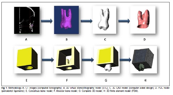
CT (computed tomography) images (0.3 mm thick) (GE HiSpeed NX/i CT scanner- General Electric, Denver, CO, USA) of a maxillary first right molar were used to build a 3D virtual stereolithography model (STL) using InVesalius 3.0b (Renato Archer Center for Information Technology, Campinas, SP, Brazil) (Figures 1A, 1B). STL was transferred to Rhinoceros 5.0 (McNeel & Associates, Seattle, WA, USA) for geometry acquisition, where the STL model was converted into a 3D CAD (computer aided design) model (Figure 1C). In the same software, both the alveolar and cancellous bones were designed as a block around the tooth (Figures 1E, 1F, 1G). The periodontal ligament was built based on the space between the tooth and the cancellous bone with a 0.25 mm thickness (Figure 1D).
FE Modeling
The geometry was imported into ANSYS v14 (Ansys, Inc., USA) for the construction of a 3D finite element model (FEM) (Figure 1H). The block, which includes the teeth, cortical and cancellous bones and periodontal ligament, consisted of 515,194 nodes and 294,042 tetrahedral elements. This study was previously approved by the University Committee on Ethics in Human Research as part of another work (084/2013).
Material Properties
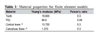
The structures were considered as linear elastic and isotropic, with an elastic modulus and Poisson's ratio for the tooth12, PDL (periodontal ligaments)12, cortical and cancellous bones13, applied to the entire model as shown in Table 1. The characterization of this material is defined by a geometrical study of the bone.
Loading and Boundary Conditions
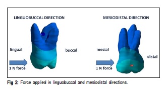
To simulate a distal tipping force on the maxillary molar, a 1 N force5 was applied on the mesial surface of the maxillary first molar crown, perpendicular to its long axis.
To simulate a buccal tipping force on the maxillary molar, a 1 N force5 was applied on the lingual surface of the maxillary first molar crown, perpendicular to its long axis (Figure 2).
Boundary conditions were attributed to the lateral and posterior faces of the block.
FE Analysis
For the results analysis was evaluated the arrows' initial displacement. Initial displacement values (Mpa) were measured with a scale and the color scale evaluated the maximum (red areas) and the minimum (blue areas) displacement points.
Results
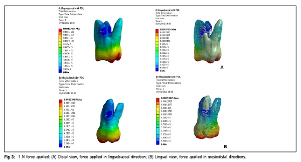
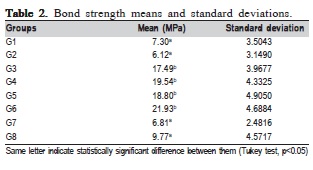
When force was applied to the crown in the linguobuccal direction, the molar rotated its axis in mesiodistal direction. This axis represents a straight line running through the middle third portion between the buccal and lingual roots. The maximum displacement recorded for this movement was 60.455 x 10⁻⁴ mm (Figure 3A).
When force was applied to the crown in the mesiodistal direction, the molar rotated its axis in linguobuccal direction. This axis represents a straight line running through the cervical third portion between the mesiobuccal and distobuccal roots of the maxillary molar. The maximum displacement recorded for this movement was 53.415 x 10⁻⁴ mm (Figure 3B).
The maximum displacement recorded for this model was 53.415 x 10⁻⁴ mm in the mesiodistal direction and 60.455 x 10⁻⁴ mm in the buccolingual direction (Table 2).
Discussion
The rotation axis may lie within or outside the tooth and represents a fixed straight line around which the tooth appears to rotate4. By calculating pure rotational and pure tipping movements, Vollmer defined the rotation center of a canine model as the one located on the long axis of the tooth, approximately 8.2 mm below the alveolar crest and two-fifths of the root length from the alveolar margin14. In this simulation, the rotation axis was restricted to the tooth and the virtual space between the roots for both movement directions (mesiodistal and linguobuccal) at the cervical and middle third of the maxillary molar roots, respectively.
Maxillary molars are known for rotating around an axis perpendicular to movement, which varies according to its direction, tooth anatomical conditions and force magnitude15-16. However, it has not been reported whether a tooth has a single center of resistance (CRes) or whether the CRes also depends on the displacement direction. Meyer et al.5 concluded, after comparing different locations of the CRes in the buccolingual and mesiodistal directions of the mandibular central incisors of 6 dogs, that the location of the CRes for buccolingual tooth movement is significantly more apical than its mesiodistal counterpart. They found presence of twodimensional axes not crossed in the buccolingual (BL) and mesiodistal (MD) directions. In the present study, the rotation axis was found reaching some points between the cervical and middle thirds of the maxillary molar roots.
For distal tipping, the rotation axis was located in the furcation of the first molar (Figure 3), whereas this axis shifted to the cervical and middle thirds of the roots for buccal tipping (Figure 3). This variation in location of the rotation axes proves the hypothesis of two-dimensional axes that do not converge, as suggested by Meyer5 in his study. Since there is no convergence of these axes, it may be stated that there is neither a common point nor a single CRes for the maxillary molar, but two-dimensional axes that appear to depend on the direction of the tooth movement. Confirming our results, Viecilli7 states that the couple-generated rotation axes do not intersect in 3 dimensions; therefore, they do not determine a 3-dimensional center of resistance.
At the same time, in order to understand the location of the center of rotation, the relationship between the force application area and the rotation axis of the tooth should be observed, taking into account the shape, length, number and location of the roots, as well as the level of the alveolar bone17-18.
A two-dimensional mathematical model showed that the most occlusal and apical locations of the CRes correspond to triangular and rectangular root shapes, respectively19. A rootlike shape produced a more apically located CRes than was experimentally measured by Yoshida et al.20. These results indicate that the more tapered the root, the more occlusal the CRes. This trend seems reasonable since the apical root region cross-sectional area decreases with more taper and therefore produces relatively less resistance to root motion near the apex. In addition to this, the buccal roots of maxillary molars consist of a flattened mesiodistal face, while the lingual root is more rounded and larger. This might account for the lower mesiodistal displacement observed in this simulation. In the buccolingual direction, the higher displacement values might be caused by the lower resistance generated by the mesiobuccal and distobuccal roots due to their shape (Table 2).
Since our model was based on a single anatomy, some characteristics of force transfer cannot be generalized21. Therefore, this study aimed to analyze the transfer of orthodontic loads in real tooth morphology other than an unrealistic model, since it is believed that the behavior of natural teeth is similar in real situations, even among different individuals.
The FEM has proven efficient in the evaluation of tooth displacement resulting from orthodontic forces. Based on this simulation, rotation axis for distal tipping is located on the furcation of the maxillary first molar, while this axis shifts to the cervical and middle third of buccal roots for buccal tipping. The initial displacement of the maxillary first molar was greater for distal tipping than for buccal tipping, due to less root resistance in this kind of movement. There is no three-dimensional rotation axis for the maxillary molar, but two-dimensional axes that do not meet and depend on the direction of tooth movement.
Among the important variables to be considered while evaluating tooth displacement using finite element models are the inclusion of periodontal ligament22, the correct selection of tooth to be modeled, the quality of CT images and the interpretation of results when compared to those concerning clinical and experimental studies.
In our study, the thickness of the periodontal ligament was assumed to be uniform (0.25 mm), whereas in reality, it has an hour-glass shape with the narrowest zone at the midroot level23, so we must consider this limitation in the design of this study. Nonetheless, when supplemented with clinical research, the findings of this study may be effectively applied to clinical situations as small dental movements like buccal or lingual maxillary molars tipping with intermaxillary elastics or maxillary molars distalization with intra oral appliances.
The applied movement interferes in molar Cres location. It is expected that higher molar tipping is expected when distal movement is applied rather than buccal movement, thanks to close distance between Cres and location of the force applied to this movement.
Acknowledgements
This research was supported by CAPES (Coordination for the improvement of Higher Education Personnel) is the Brazilian Federal Agency for the Support and Evaluation of Graduate Education. The authors would like to thank Dr. Alexandre R. Freire for his help with the finite element model construction.
References
1. Rudolph DJ, Willes PMG, Sameshima GT. A finite element model of apical force distribution from orthodontic tooth movement. Angle Orthod. 2001; 71: 127-31. [ Links ]
2. Cattaneo PM, Dalstra M, Melsen B. Moment-to-force ratio, center of rotation, and force level: a finite element study predicting their interdependency for simulated orthodontic loading regimens. Am J Orthod Dentofacial Orthop. 2008; 133: 681-9.
3. Bourauel C, Keilig L, Rahimi A, Reimann S, Ziegler A, Jager A. Computeraided analysis of the biomechanics of tooth movements. Int J Comput Dent. 2007; 10: 25-40.
4. De Pauw G, Dermaut L, De Bruyn H. The value of the centre of rotation in initial and longitudinal tooth and bone displacement. Eur J Orthod. 2003; 25: 285-91.
5. Meyer BN, Chen J, Katona TR. Does the center of resistance depend on the direction of tooth movement? Am J Orthod Dentofacial Orthop. 2010; 137: 354-61.
6. Reimann S, Keilig L, Jager A, Bourauel C. Biomechanical finite-element investigation of the position of the centre of resistance of the upper incisors. Eur J Orthod 2007; 29: 219-224.
7. Viecilli RF, Budiman A, Burstone CJ. Axes of resistance for tooth movement: does the center of resistance exist in 3-dimensional space? Am J Orthod Dentofacial Orthop. 2013; 143: 163-72.
8. Aruna J. A study on evaluation of center of resistance of maxillary four incisors during simultaneous intrusion and retraction: a finite element study. J Pharm Bioallied Sci. 2014; 6(Suppl 1): S49-51.
9. Schneider J, Geiger M, Sander F. Numerical experiments on long-time orthodontic tooth movement. Am J Orthod Dentofacial Orthop. 2002; 121: 257-65.
10. Nakajima A, Murata M, Tanaka E, Arai Y, Fukase Y, Nishi Y et al. Development of three-dimensional FE modeling system from the limited cone beam CT images for orthodontic tipping tooth movement. Dent Mater J. 2007; 26: 882-91.
11. Ammar HH, Ngan P, Crout RJ, Mucino VH, Mukdadi OM. Threedimensional modeling and finite element analysis in treatment planning for orthodontic tooth movement. Am J Orthod Dentofacial Orthop. 2011; 139: e59-71.
12. Tanne K, Yoshida S, Kawata T, Sasaki A, Knox J, Jones ML. An evaluation of the biomechanical response of the tooth and periodontium to orthodontic forces in adolescent and adult subjects. Br J Orthod. 1998; 25: 109-15.
13. Ko CC, Chu CS, Chung KH, Lee MC. Effects of posts on dentin stress distribution in pulpless teeth. J Prosthet Dent. 1992; 68: 421-7.
14. Vollmer D, Bourauel C, Maier K, Jager A. Determination of the centre of resistance in an upper human canine and idealized tooth model. Eur J Orthod. 1999; 21: 633-48.
15. Liu DX, Wang CL, Fu CY, Zhang XY, Zheng XZ. [FEM study on displacement, position of rotation center and stress distribution of PDL under various loading force systems]. Hua Xi Kou Qiang Yi Xue Za Zhi. 2004; 22: 192-5.
16. Qian H, Chen J, Katona TR. The influence of PDL principal fibers in a 3- dimensional analysis of orthodontic tooth movement. Am J Orthod Dentofacial Orthop. 2001; 120: 272-9.
17. Fang BJ, Zhou Q, Wang JS. Three dimensional finite element analysis of the upper incisor with different levels of periodontal support. Shanghai Kou Qiang Yi Xue. 2006; 15: 313-7.
18. Geramy A. Initial stress produced in the periodontal membrane by orthodontic loads in the presence of varying loss of alveolar bone: a three-dimensional finite element analysis. Eur J Orthod. 2002; 24: 21-33.
19. Choy K, Pae EK, Park Y, Kim KH, Burstone CJ. Effect of root and bone morphology on the stress distribution in the periodontal ligament. Am J Orthod Dentofacial Orthop. 2000; 117: 98-105.
20. Yoshida N, Jost-Brinkmann PG, Koga Y, Mimaki N, Kobayashi K. Experimental evaluation of initial tooth displacement, center of resistance, and center of rotation under the influence of an orthodontic force. Am J Orthod Dentofacial Orthop. 2001; 120: 190-7.
21. Cattaneo PM, Dalstra M, Melsen B. The finite element method: a tool to study orthodontic tooth movement. J Dent Res. 2005; 84: 428-33.
22. Fill T, Toogood R, Major P, Carey J. Analytically determined mechanical properties of, and models for the periodontal ligament: Critical review of literature. J Biomechs. 2012; 45: 9-16.
23. Sunga E, Kima S, Chunb Y, Parka Y, Yua H, Leea K. Distalization pattern of whole maxillary dentition according to force application points. Korean J Orthod. 2015; 45: 20-8.
 Correspondence:
Carla Scanavini Croci
Universidade Estadual de Campinas
Faculdade de Odontologia de Piracicaba
P.O. Box 52
13414-903, Piracicaba, SP, Brazil
E-mail: cscanavini@hotmail.com
Received for publication: February 18, 2015
Accepted: June 02, 2015
