


Serviços Personalizados
Artigo
 pdf em Inglês
 Artigo em XML
 Referências do artigo
 Enviar este artigo por email
Links relacionados
Compartilhar

 Permalink
RGO.Revista Gaúcha de Odontologia (Online)
versão On-line ISSN 1981-8637
RGO, Rev. gaúch. odontol. (Online) vol.61 no.4 Porto Alegre Out./Dez. 2013
ORIGINAL / ORIGINAL
Bone stress evaluation in implants with Regular and Switching platforms
Avaliação da tensão óssea em implantes com plataforma Regular e Switching
Nália Cecília GURGEL-JUAREZI; Fabiana Mantovani Gomes FRANÇAI; Sidney KINAI; Érika Oliveira de ALMEIDAII; Eduardo Passos ROCHAII
I Faculdade São Leopoldo Mandic, Curso de Odontologia, Programa de Pós-Graduação em Prótese Dental. Rua José Rocha Junqueira, 13, Swift, 13045-755, Campinas, SP, Brasil.
II Universidade Estadual Paulista Júlio de Mesquita Filho, Faculdade de Odontologia. Araçatuba, SP, Brasil.
ABSTRACT
Objective
Considering that the bone stress caused by the internal hexagon implant is lower in comparison with that caused by external hexagon implant, the aim of this study was to evaluate stress distribution of the peri-implant bone, by simulating the influence of the switching platform in external hexagon implants in comparison with regular platform in the internal hexagon implant.
Methods
TTwo mathematical models of an implant-supported central incisor were created: Regular (R), 4.5 x 11.5 mm internal hexagon implant and 4.5 mm abutment and Switching (S), 5.0 x 11.5 mm external hexagon implant and 4.1 mm abutment. The models were created using the SolidWorks 2010 (3Dtech, São Paulo, Brazil) program. Oblique forces (100 N) were applied to the palatine surface of the central incisor. The bone/implant interface was considered perfectly integrated. Maximum and minimum principal stress values were evaluated in the cortical and medullary bones. The numerical analysis was performed using the ANSYS Workbench 10.0 (Swanson Analysis System, Houston, Pa).
Results
For the cortical bone, the highest stress values were observed in the R (48.8 MPa), followed by the S (48.5 MPa). For the medullary bone, the highest stress values were observed in the S (3.66 MPa), followed by the regular (1.51 MPa).
Conclusion
External hexagon implant with switching platform showed a biomechanical performance similar to that of the internal hexagon implant with regular platform in the cortical bone analysis. Whereas, for the medullary bone, the switching platform model transmitted more stress than the regular model.
Indexing terms: Biomechanics. Dental implantation. Finite element analysis. Maxilla. Osseointegration.
RESUMO
Objetivo
Avaliar a distribuição de tensão no osso peri-implantar de implante hexágono interno com plataforma regular e implante hexágono externo com plataforma switching.
Métodos
Foram confeccionados dois modelos matemáticos representativos de uma maxila parcial da região do elemento 11, sendo um modelo Regular, com implante hexágono interno (4,5 x 11,5 mm) e pilar 4,5 mm e outro modelo Switching, com implante hexágono externo (5,0 x 11,5 mm) e pilar 4,1 mm. Ambos os modelos continham uma coroa cimentada sobre o pilar do implante. Os modelos foram desenvolvidos pelo programa SolidWorks 2010 (3Dtech, São Paulo, Brasil). Forças oblíquas (100 N) foram aplicadas na face palatal das coroas. A interface osso-implante foi considerada perfeitamente integrada. Máxima e mínima tensão principal foram avaliadas no osso cortical e medular. A análise numérica foi realizada através do programa ANSYS Workbenck 10,0 (Swanson Analysis System, Houston, Pa).
Resultados
No osso cortical, os maiores valores de tensão foram observados para R (48,8 MPa), seguido de S (48,5 MPa). Para o osso medular, os maiores valores de tensão foram observados no modelo S (3,66 MPa), seguido por R (1,51 MPa).
Conclusão
O modelo switching apresentou comportamento biomecânico semelhante ao modelo de plataforma regular na análise do osso cortical. Enquanto que no osso medular, o modelo switching transmitiu mais tensão óssea do que o modelo Regular.
Termos de indexação: Biomecânica. Implantação dentária. Análise de elementos finitos. Maxila. Osseointegração.
INTRODUCTION
The Branemark type of implant (Nobelpharma AB, Gothenburg, Sweden) is the most widely distributed on the market worldwide, and has been the most classical and most studied model since the 1960s. Researches conducted with these external hexagon implant have obtained favorable responses in the rehabilitation of edentulous mandibles and with partial dental prostheses1-2.
One year after these external hexagon implants entered into function, a bone loss up to the level of the first thread of the implant was observed3. This situation was so common that in the first reports on criteria for osseointegration, Albrektsson et al.4 and Smith & Zarb5 included peri-implant calciform resorption as one of the determinant factors of success.
This bone loss could also be observed with the use of the internal hexagon type of implants. In comparison with the external hexagon, the internal connection has presented better performance in laboratory tests and those of structural integrity of the maxillary implant 6, antirotational stability6, low rate of abutment screw loss7 and lower stress transmitted to bone8.
In spite of the internal hexagon implants presenting these better mechanical properties with regard to the type of connection, they equally exhibit cup-shaped bone resorption around the head of the implant when they enter into function9.
As the longevity of dental implants depends on integration between the implant components and hard and soft tissues of the oral cavity10, various authors began to study the causes of bone resorption.
The factors most frequently mentioned as possible causes of this loss are: Occlusal overload11-18, contamination of the microspace between the abutment and implant19, re-establishment of biologic space19, the implant neck design10-20-21, surgical trauma10, peri-implantitis10 and the gingival biotype22.
Although there is still no consensus in the literature with regard to the factor triggering peri-implant resorption, it is of the utmost importance to know when the peri-implant bone loss attains a stable level, because preservation of the supporting bone is essential for the esthetics of the soft tissues21,23. With the increasing requirement by esthetically demanding patients, the search for more natural restorations has been a challenge to clinicians.
Within this context, absence or minimal bone loss would be ideal. An approach suggested by Lazzara & Porter24 was to alter the horizontal relationship between the implant diameters and those of the prosthetic component, thus introducting the platform switching concept. The principle of this technique consists of the prosthetic component diameter being smaller than the implant diameter24, which has been studied a great deal and widely disseminated in the literature.
Clinical, radiographic and histological studies have shown a reduction in peri-implant bone loss with the use of platform switching19,21,25-26. Researches using the finite element method have shown a more uniform distribution of force on the peri-implant bone with platform switching in comparison with the traditional technique9,12-13,15-16.
Therefore, the aim of this study was to evaluate the different stress distributions on the bone around internal hexagon implants with traditional platforms, and external hexagon implants with platform switching.
METHODS
This study was approved by the Research Ethics Committee of the Araçatuba School of Dentistry (UNESP) under Protocol No. 2008/01845. After signing the Term of Free and Informed Consent, the patient was submitted to tomographic examination of the maxilla, from which a section of the right maxillary central incisor region, cortical and trabecular bone were obtained in dicom format. The mathematical models of the representation of this segment of the maxilla were fabricated using the software programs Mimics 11,11 (Materialise, Leuven, Belgium) and Solidworks (SolidWorks Corp., Concord, MA, USA).
To generate the geometrical models of the implants and prosthetic components of the SIN system (Sistema de Implantes, São Paulo, SP, Brazil), high definition photographs were taken with the aid of static and digital pachymeters (Mitutoyo Corp., Tokyo, Japan) to determine the measurements of the materials. The images were imported into the SolidWorks software program in .tif format for dimensioning, where the final models were made.
Two models were created: R, with an internal hexagon type of implant of the SIN system (Sistema de Implante, São Paulo, Brazil) Strong (4.5 x 11.5 mm) and regular platform (abutment diameter: 4,5 mm); S, with an external hexagon type of implant of the SIN system (Sistema de Implante, São Paulo, Brazil) Strong (5.0 x 11.5 mm) and platform switching (abutment diameter: 4.1 mm). The crown measurements were maintained constant in both models, presenting a height of 13 mm, mesio distal width of 8.8 mm and vestibular-palatal distance of 7.1 mm.
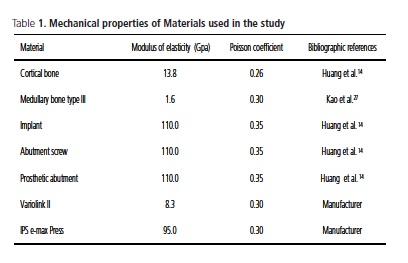
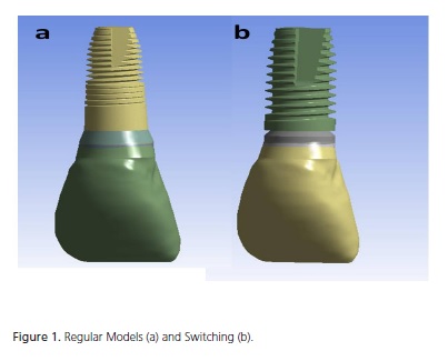
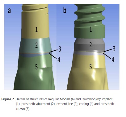
The mathematical models consisted of a total crown made of IPS e-max Press (Ivoclar Vivadent, Schaan, Liechtenstein) cemented onto the preparable prosthetic abutment that was screw-retained on the implant, with representation of the cortical bone (1 mm) and medullary bone perfectly united to one another. The soft tissues in the region were not considered. The dimensions of all the structures, with the exception of the type of implant and prosthetic abutment were maintained constant. Simulation of crown cementation on the prosthetic abutments was performed with a 0.05 mm thick layer of Variolink II (Ivoclar Vivadent, Schaan, Liechtenstein) adhesive cement (Figure 1 and 2).
These models were exported to the ANSYS Workbench 10.0 (Swanson Analysis Inc. Houston, Pa, USA) software program, for recognition of the regions, determination of the mechanical properties, and generation of the finite element meshes.
The mechanical properties of the Modulus of Elasticity (E) and Poisson Coefficient () of each structure were used to consider the study homogeneous, isotropic and linearly elastic (Table 1). The mechanical properties refer to a bone quality type III, according to the classification of Lekholm & Zarb28, as this type of bone is more prevalent in the anterior region of the maxilla29. The bone-implant contact interface was considered completely osseointegrated.
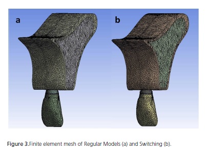
A solid element for parabolic tetrahedron interpolation30 and a mesh composed of elements measuring 0.8mm were used. Model R had 167,899 knots and 105,185 elements; and Model S had 226,966 knots and 142,078 elements (Figure 3).
As the contour condition, there was fixation of all the knots in the mesial and distal regions of the model. All the knots were fixed to the 3 Cartesian axes X, Y and Z.
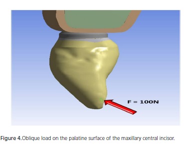
An oblique (45°) loading (C) of 100 N on the palatal surface of the maxillary central incisor was adopted (Figure 4).
The stress maps with maximum and minimum principal stress (αmax e αmin), in MPa, were obtained for the cortical and medullary bone. This criterion of analysis was selected due to the fact that bone is not a ductile material, but a friable material, in addition to presenting tensile stress values differing from the compression stress values.
RESULTS
Table 2 shows the numerical results obtained in the study. From a general aspect, the value of αmax on cortical bone was similar for the two models. On medullary bone, Model S presented higher max.
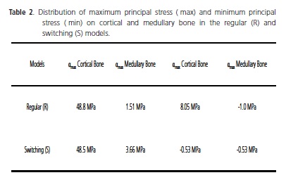
In a specific manner for the cortical bone, Model R presented an αmax value (48.8 MPa) close to that of model S (48.5 MPa), with the difference in values found being around 0.6%. More divergent results were observed as regards the αmin values (8.05 MPa for Model R and -0.53 MPa for Model S). In addition to the second model having shown compression stress, there was a reduction of 93.41% in the value of αmin for this group in comparison with the first model (Table 2).
For the medullary bone, the αmax value in Model S was higher (3.66 Mpa) than the value observed in Model R (1.51 Mpa) by 142.38%. To the contrary, the minimum stress (αmin) for Model S was lower (-0.53 Mpa) when compared with the value observed for Model R (-1.0 Mpa) by 47%. In addition, it was observed that both αmin values demonstrated compression stress (Table 2).
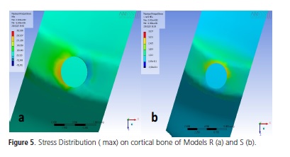
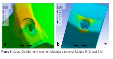
In model R, higher stress concentration was observed in the proximal region of cortical bone with reference to the implant platform, represented by the warm colors in the stress maps (Figure 5) . The same region of stress concentration was observed in the medullary bone, however, with greater extension towards the apical region, as may be observed in Figure 6.
In Model S, the highest stress concentration occurred on the palatine surface of cortical bone (Figure 5). Whereas on the medullary bone of this model, the highest concentration of stress was observed on the palatine and vestibular surfaces (Figure 6).
DISCUSSION
The finite element method has been an important computational tool, widely used for biomechanical analysis of implants, implant supported dental prostheses and peri-implant tissues. Quaresma et al.13 have pointed out the advantage that virtual models have of allowing the evaluation of specific factors, without the influence of other variables.
As has occurred in other studies15,29-30, in the present study some simplifications were admitted with reference to the characterization of the studied materials being considered homogeneous, isotropic and linearly elastic. In the literature, there are studies29 that have used more in-depth methods to determine the characterization of dental materials, such as the determination of possible existent non linearities, anisotrophy or orthotropy and heterogeneities.
In this type of method, certain simplifications are admitted, such as considering the studied materials being homogeneous, istotropic and linearly elastic, in order to make the processes of modeling and resolution possible. Nevertheless, some authors defend the realization of nonlinear, anisotropic and heterogeneous studies29.
With regard to the comparison between implants of different diameters, used in this study, this was also the methodology that has been used by various authors9,13-14,16-17,25. According to the studies of Ding et al.17, the differences in behavior between implants with diameters of 4.1 and 4.8 mm (0.7 mm of difference between the platforms) were not notable. In the present study, the difference between the implant diameters was still less, to the order of 0.5 mm (implants with platforms of 4.5 and 5 mm).
This study considered perfect union of the bone-implant interface, with 100% osseointegration, in accordance with the literature13,15,29.
The force of loading was 100N, as in the studies in the literature13,15. This force with oblique load on the maxillary central incisor in the palatine-vestibular direction simulated that which occurs physiologically, and was also used by Saab et al.29, who affirmed that this provides better conditions for analyzing the behavior of the studied implants, with bone responses within the physiological limits. Furthermore, the literature is unanimous in affirming that implants submitted to inclined forces transfer more stress to the adjacent bone15,17-18.
When an implant is submitted to inclined loads in relation to its long axis, the highest stress generated is located on the cortical bone around the neck of the implant12,13-18. In this study, this result was also observed, so that for Model R, the concentration of this stress occurred specifically in the proximal regions. Whereas in Model S, the stress was more evident in the palatine region, suggesting a better behavior in an esthetic area when platform switching is used, because, less stress transmitted to the proximal bone may involve less bone loss in this region.
Analysis of this cortical bone showed that Groups R and S presented a similar behavior when the maximum principal stress (αmax) was verified in the models, since Group R presented slightly higher αmax (48.8 MPa) than Group S (48.5 MPa). However, one could speculate that the increase in implant diameter could result in less tension transmitted to the cortical bone, as various authors have affirmed14,17-18.
Rodríguez-Ciurana et al.9 also found no significant difference between the stresses presented by the external hexagon implant models with a diameter of 5 mm and internal hexagon with a diameter of 4.8 mm on cortical bone – dimensions close to those used in the present study; however, both models had a 4.1 mm abutment. Maeda et al.12 observed higher stress concentration around the regular implant when compared with the implant with platform switching, in his tridimensional models; this was similar to the effect that occurred in the S and R models. Quaresma et al.13 found higher stress on the cortical bone around the internal hexagon implant than the platform switching implant (characteristic of the implant design with internal conical connection used by the authors). However, the values found in the study of these authors13 were more discrepant, and not as close to the values of the present study - probably due to the internal conical connection used by the authors.
When the minimum principal tension (αmin) on cortical bone was analyzed, Group R presented tensile stress (8.05 MPa), whereas Group S presented compression stress (-0.53 MPa). Therefore, both αmax and αmin in Group R were tensile stresses, whereas in Group S tensile (αmax) and compression (αmin) stresses were found. These results are similar to those found by Baggi et al.16, because their implant model with platform switching presented tensile and compression stresses on the cortical bone.
The study of medullary bone showed that the maximum principal stress was higher for Group S (3.66 MPa) than for Group R (1.51 MPa). This means that the implant with a larger diameter (S: 5 mm) transmitted more stress to the medullary bone than the implant with the 4.5 mm platform (R), which is in agreement with the findings in the literature13,17. The explanation for this result is the probable reduction in the quantity of medullary bone when the implant diameter is increased17. According to Holmgren et al.11, this result shows that the wider implant is not necessarily the best choice because in cases with morphological limits, the stress distribution on the bone is unfavorable. However, when one takes the cortical bone into consideration, the larger implant diameter transfers less bone stress11,14,17-18 and Ding et al.17 affirmed that an implant with a wider cervical portion may dissipate masticatory forces better, thereby diminishing bone loss. Thus, from a biomechanical perspective, these authors suggest the choice of an implant with the maximum diameter allowed by the anatomy of the region.
From the point of view of the type of hexagon of each implant, this study showed that the internal connection generated 142% less stress on the medullary bone than that generated by the external connection, which is in harmony with the results of Baggi et al.16, in which the external hexagon generated around three times more bone stress than the internal hexagon.
In the studied models, the stress concentration on the medullary bone occurred in the cervical region. For Model S this stress was located on the vestibular and palatine surfaces, whereas for Model R stress was concentrated in the proximal region with greater extension in the apical direction. Without specifying the surfaces, some authors obtained stress concentration in the cervical region of the medullary bone around the implant9,16-17. However, for the cortical bone thickness of 1 mm (used in this study), Okumura et al.18 reported stress concentration on the apex of the implant; these authors found stress in the cervical region only for the simulated corticals of 0.5 and 0 mm. This difference possibly occurred because the simulation used by these authors18 was of the posterior maxilla, with different dimension from those of the model used in the present study, and modeling of the maxillary sinus. The behavior of apical stress propagation of Model R being more perceptible in Model S was also observed in the study of Maeda et al.12.
It is known that the implant with an internal hexagon has a more favorable biomechanical performance than that of the implant with an external hexagon6-8, in spite of the external hexagon, classically, still being the platform most frequently used. There is also common accord in the literature that platform switching has diminished bone loss around the neck of the implant9,12-13,15-16,19,21,24-26.
Therefore, it could be affirmed that within the limitations of this study, the use of the wide external hexagon implant with the platform switching principle obtained a similar performance to that of an internal hexagon implant with a regular platform, in the anterior maxilla, with regard to stress transmission to the cortical bone (which is the region were bone loss begins).
CONCLUSION
According to the methodology used, it could be concluded that for cortical bone, implants with the external hexagon type of connection, using the principle of platform switching, have a similar biomechanical performance to that of internal hexagon implants and platform diameter coinciding with that of the prosthetic platform.
Whereas, for medullary bone, the external hexagon implant model with platform switching transmitted higher bone tension than the internal hexagon implant model with a regular platform.
Collaborators
NCG JUAREZ conducted the scientific research, and performed the entire bibliographic survey and writing of the article. FMG França guided the research and participated in writing the article. S KINA was responsible for the idea of the work and participated actively in correction, carrying out the work and writing the article. ÉO Almeida fabricated all the tridimensional computational models, and together with NCG JUAREZ, performed the laboratory tests of the study. He participated actively in writing the article. EP ROCHA co-oriented the research, made the partnership between the institutions feasible for the development of the study. He guided the author ÉO ALMEIDA in fabrication of the computational models and helped to conduct and structure the entire development of the study. He participated in writing the article.
REFERENCES
1. Branemark P-I, Adell R, Breine U, Hansson BO, Lindström J, Ohlsson A. Intra-osseous anchorage of dental prosthesis. Experimental studies. Scand J Plast Reconstr Surg. 1969;3(2):81- 100. [ Links ]
2. Jemt T, Chai J, Harnett J, Heath MR, Hutton JE, Johns RB. A 5-year prospective multicenter follow-up report on overdentures supported by ossseointegrated implants. Int J Oral Maxillofac Implants. 1996;11:291-8.
3. Adell R, Lekholm U, Rockler B, Branemark P-I, Lindhe J, Eriksson B, et al. Marginal tissue reactions at osseointegrated titanium fixtures. A 3 year longitudinal prospective study. Int J Oral Maxillofac Implants. 1986;15(1):30-52.
4. Albrektsson T, Zarb GA, Worthington P, Eriksson AR. The longterm efficacy of currently of currently used dental implants: a review and proposed criteria of success. Int J Oral Maxillofac Implants. 1986;1(1):11-25.
5. Smith DE, Zarb GA. Criteria for success of osseointegrated endosseous implants. J Prosthet Dent. 1989;62(5):567-72. doi: 10.1016/0022-3913(89)90081-4.
6. Möllersten L, Lockowandt P, Lindén L-A. Comparison of strength and failure mode of seven implant systems: an in vitro test. J Prosthet Dent. 1997;78(6):582-91. doi: 10.1016/S0022- 3913(97)70009-X.
7. Krennmair G, Schmidinger S, Waldenberger O. Single-tooth replacement with the Frialit-2 system: a retrospective clinical analysis of 146 implants. Int J Oral Maxillofac Implants. 2002;17(1):78-85.
8. Bernardes SR, de Araujo CA, Neto AJ, Simamoto Junior P, das Neves FD. Photoelastic analysis of stress patterns from different implant-abutment interfaces. Int J Oral Maxillofac Implants. 2009;24(5):781-90.
9. Rodriguez-Ciurana X, Vela-Nebot X, Segala-TorreS M, Rodado- Alonso C, Mendez Blanco V, Mata-Buguelores. Biomechanical repercussions of bone resorption related to biologic width: a finite element analysis of three implant-abutment configurations. Int J Periodontics Restorative Dent. 2009;29(5):479-87.
10. Oh T-J, Yoon J, Misch CE, Wang H-L. The causes of early implant bone loss: myth or science? J Periodontol. 2002;73(3):322-33.
11. Holmgren EP, Seckinger RJ, Kilgren LM, Mante F. Evaluating parameters of osseo integrated dental implants using finite element analysis-a two dimensional comparative study examining the effects of implant shape, and load direction. J Oral Implantol. 1998;24(2):80-8. doi: 10.1563/1548-1336(1998)024<0080:EP OODI>2.3.CO;2.
12. Maeda Y, Miura J, Taki I, Sogo M. Biomechanical analysis on platform switching: is there any biomechanical rationale? Clin Oral Impl Res. 2007;18(5):581-84. doi: 10.1111/j.1600- 0501.2007.01398.x.
13. Quaresma SET, Cury PR, Sendyk WR, Sendyk C. A finite element analysis of two different dental implants: stress distribution in the prosthesis, abutment, implant, and supporting bone. J Oral Implantol. 2008;34(1):1-6. doi: 10.1563/1548-1336(2008)34[1:AFEAOT]2.0.CO;2.
14. Huang HL, Hsu JT, Fuh LJ, Tu MG, Ko CC, Shen YW. Bone stress and interfacial sliding analysis of implant designs on an immediately loaded maxillary implant: a non-linear finite element study. J Dent. 2008;36(6):409-17. doi: 10.1016/j. jdent.2008.02.015.
15. Schrotenboer J, Tsao YP, Kinariwala V, Wang H L. Effect of microthreads and platform switching on crestal bone stress levels: a finite element analysis. J Periodontol. 2008;79(11):2166- 72. doi: 10.1902/jop.2008.080178.
16. Baggi L, Cappelloni I, Di Girolamo M, Maceri F, Vairo G. The influence of implant diameter and length on stress distribution of osseointegrated implants related to crestal bone geometry: a three-dimensional finite element analysis. J Prosthet Dent. 2008;100(6):422-31. doi: 10.1016/S0022-3913(08)60259-0.
17. Ding X, Zhu X-H, Liao S-H, Zhang X-H, Chen H. Implant-bone interface stress distribution in immediately loaded implants of different diameters: a three-dimensional finite element analysis. J Prosthodont. 2009;20:1-10.
18. Okumura N, Stegaroiu R, Kitamura E, Kurokawa K, Nomura S. Influence of maxillary cortical bone thickness, implant design and implant diameter on stress around implants: a three-dimensional finite element analysis. J Prosthodont Res. 2010. doi: 10.1016/j. jpor.2009.12.004.
19. Jung RE, Jones AA, Higginbottom FL, Wilson TG, Schoolfield J, Buser D, et al. The influence of non-matching implant and abutment diameters on radiographic crestal bone levels in dogs. J Periodontol. 2008;79(2):260-70. doi: 10.1902/ jop.2008.070132.
20. Jung YC, Han CH, Lee KW. A 1-year radiographic evaluation of marginal bone around dental implants. Int J Oral Maxillofac Implants. 1996;11(6):811-8.
21. Shin T-K, Han C-H, Heo S-J, Kin S, Chun H-J. Radiographic evaluation of marginal bone level around implants with different neck designs after 1 year. Int J Oral Maxillofac Implants. 2006;21(5):789-94.
22. Evans CD, Chen ST. Esthetic outcomes of immediate implant placements. Clin Oral Implants Res. 2008;19(1):73-80. DOI: 10.1111/j.1600-0501.2007.01413.x.
23. Tarnow D, Elian N, Fletcher P, Froum S, Magner A, Cho S-C, et al. Vertical Distance from the crest of bone to the height of the interproximal papilla between adjacent implants. J Periodontol. 2003;74(12):1785-8. doi: doi:10.1902/jop.2003.74.12.1785.
24. Lazzara RJ, Porter SS. Platform switching: a new concept in implant dentistry for controlling postrestorative crestal bone levels. Int J Periodontics Restorative Dent. 2006;26(1):9-17.
25. Cappiello M, Luongo R, Di lorio D, Bugea C, Cocchetto R, Celletti R. Evaluation of peri-implant bone loss around platform-switched implants. Int J Periodontics Restorative Dent. 2008;28(4):347-55.
26. Guirado JLC, Ruiz AJO, Moreno GG, Mari LL, Gonzalez LAB. Immediate loading and immediate restoration in 105 expandedplatform implants via the Diem System after a 16-month followup period. Med Oral Patol Oral Cir Bucal. 2008;13(9):576-81.
27. Kao H-C, Gung Y-W, Chung T-F, Hsu M-L, Dent DM. The influence of abutment angulation on micromotion level for immediately loaded dental implants: a 3-D finite element analysis. Int J Oral Maxillofac Implants. 2008;23(4):623-30.
28. Lekholm U, Zarb GA. Patient selection and preparation. In: Branemark PI, Zarb GA, Albrektsson T. Tissue-integrated prostheses: osseointegration in clinical dentistry. Chicago: Quintessence; 1985. p.199-209.
29. Saab XE, Griggs JA, Powers JM, Engelmeier RL. Effect of abutment angulation on the strain on the bone around an implant in the anterior maxilla: a finite element study. J Prosthet Dent. 2007;97(2):85-92. doi: 10.1016/j.prosdent.2006.12.002.
30. Cook RD, Malkus DS, Plesha ME. Concepts and applications of finite element analysis: John Wiley e Sons. New York: [s.n.]; 2001.
 Endereço para correspondência:
NC Gurgel-Juarez
e-mail: naliag@yahoo.com
Received on: 13/12/2010
Final version resubmitted on: 6/9/2011
Approved on: 13/1/2012
